
This is the build of a temperature control setup for my fermenter. It’s getting cooler out this time of year so it was a good time to set up a Copper Tun heat pad to put under the fermenter and a controller to regulate the heat. I will be using a Ranco ETC-111000 digital temperature controller that I have to wire-up myself. You can buy them already set-up but doing it myself saved me some money. You’ll also need a thermowell for the controller’s temperature probe to put inside your fermenter.
Approximate times in the video are noted for reference.
Video Summary
If you are not experienced with working with high voltage wiring, you should seek the help of a qualified electrician if you attempt to perform any of the steps in this video.
It’s time to build a temperature control set up for my fermenter. It’s getting cool this time of year (snow has already started to fall) and I’ve had some trouble with brew fermentation temperatures before, so it’s time to set up a heat-pad for the bottom of the fermenter. I’ll be using a Ranco digital temperature controller and a stainless steel thermowell for the temperature probe.
You can buy the temperature controller already set up, but I saved a few bucks with this one and I will set it up myself. It comes with the probe all ready to go, I just have to wire in my actual plug and the receptacle for the heating pad. I’m going to pull it apart, wire it up, and then test it.
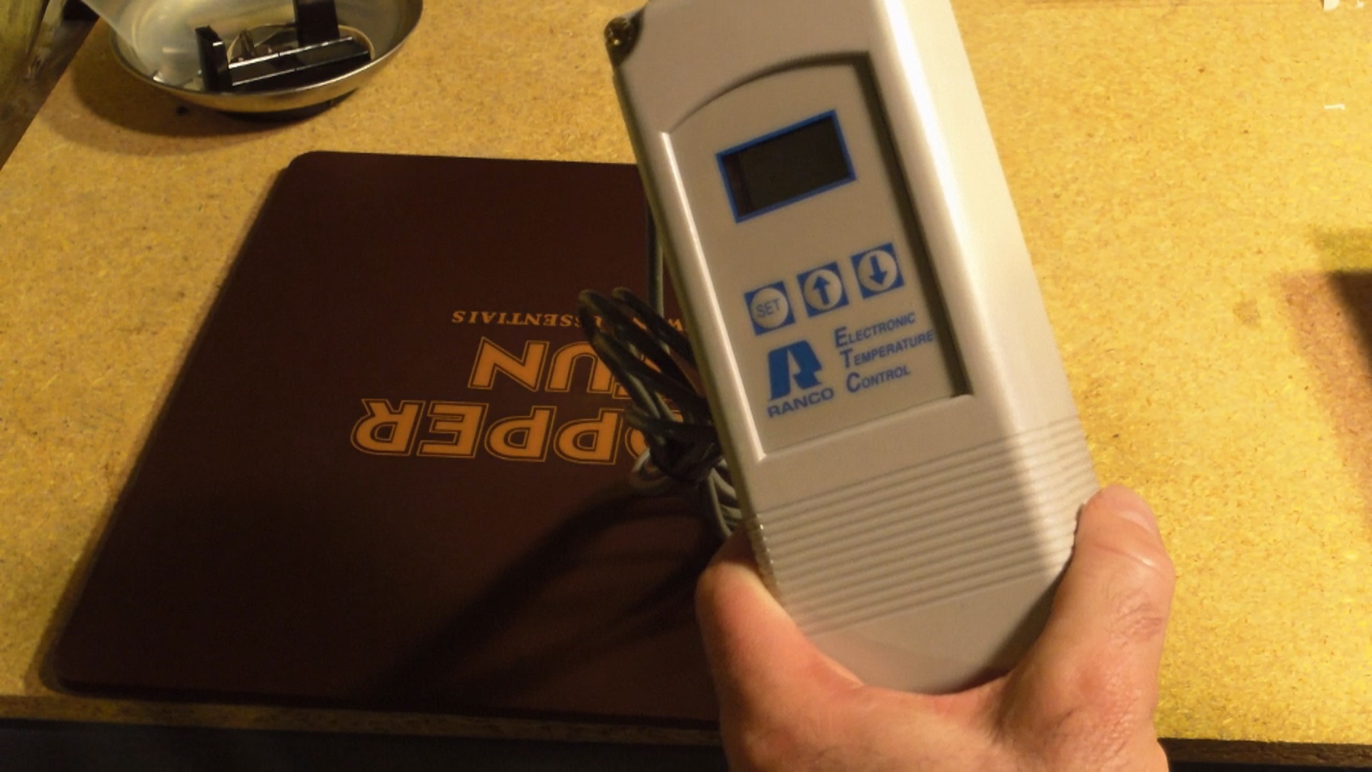
Ranco ETC 111000 Temperature Controller
1:20 The Copper Tun Brewing Essentials heat pad is made of a hard plastic. They (manufacturers) make a variety of these so there are a few options and types to choose from. It’s made for anything from plastic fermenters to glass ones. You can place anything from 6.3-7.4 gallons on it, so it’s very strong. When its on, it uses 25 watts of power.
Basically the pad sits on flat service, and you put the ferementer on top of the pad. The plug will be wired into the controller where the pad will plug into, and the probe will be placed inside the thermowell and put inside the fermenter. The top of the thermowell has two holes; one for the probe and the other for the air lock.
This controller will switch up to 16 amps (which is very large considering my pad uses about half of an amp). The controller can operate from -30 to 220 degrees F, and the differential adjustment is from 1-30 degrees F. So you could set this so it turns the heat on with as little as a 1 degree F change up to a 30 degree F change. You’ll most likely keep it at 1 degree F.
3:25 Here are the basic tools you will use: a Phillips flathead screwdriver, wire stripper, razor blade to trim wires, receptacle tester (if you have one) and a multi-meter to check and ensure you’ve wired it correctly (one easy way to tell would be to plug a lamp into it to make sure it turns on and off correctly).
3:50 We have to take out the four screws on top of the box. This model is a Ranco model, another popular model is by Johnson Controls. There are digital (more precise) and analog options for these units. I just want to get things within a decent range but I got a good price on mine, so I decided to go with the digital. This is the type of equipment where if you buy it right, you can justify getting the better version since you’ll have it for a long time.
4:40 As you look inside you can see where all the different wiring connections are. This can be wired for 120 volts (that’s what I will be wiring it for) or 240 volts. The contacts are where you will wire up the other end of the plug in order to switch the heat pad. You will need a line cord or extension cord you can cut in half. Mine is 18 gauge which is more than enough.
There are many options of plugs for the other end of the line cord. For the half inch knockout on the box you’ll need a conduit connector – mine is plastic to match the controller’s box. The other thing you can do, which is a much easier way, is to buy a short extension cord that has a connector on either end, and just cut it in half and wire it into the box.
6:00 I’m going to start by putting the conduit connector on the box. Then take the cord and wire it onto the end of the female receptacle (if you’re using and extension cord you get to skip this step). On the plug, just unscrew it and pull it apart. Then strip the line cord. If you do it with a razor blade like me, be really careful. You can’t slice too far into the other wires or you’ll break the insulation. If you do slice them and leave them like that without protection, you could be causing yourself a whole lot of trouble or even cause a fire.
So this line cord is shielded and has an extra drain wire in it. You don’t need that for this build, so just cut that off. Then, make sure to slide the outer shell of the plug into the cord first, and adjust the wires to the correct length and strip them.
7:50 The ground terminal will be the green wire, the gold terminal will be the black wire and the silver/neutral terminal will be the white wire. First twist the wire (you can tin them with solder if you want, but it’s not necessary), then make sure when you run the wire, that when you screw it back on tight it tightens and doesn’t unravel the wiring. The terminals are easily removable and the colors, although subtle, are there to guide you. Just unscrew what you can, take the wire and feed it though, then tighten ensuring it doesn’t unravel. Make sure the wire’s insulation almost touches the screw, and push down any fraying.

10:24 When replacing the terminals back into the plug (if they came out), remember that the silver is the longer side, and the gold is shorter. Once all the wiring is complete, just to hold things together, I’m going to wrap a very small amount of electrical tape around the wiring. Make sure there is not too much otherwise it will not close. Then reconnect and screw the plug back together.
11:14 Now that it is all back together; let’s make sure we wired it correctly using a receptacle tester or similar. Just stick it into the plug and make sure the lighting is correct; and mine is.
11:54 Next I’m going to cut my cord and get ready to connect it. In the next few steps you will need about a three inch piece of extra white and black electrical wire. If you do not have this lying around I suggest you cut some excess off your cord and use that. Whatever you use should be at least the same gauge. After you cut the cord, strip back both ends and wire like before, to prepare for wiring into the box. Make sure the wires are stripped back enough, you will be using wire nuts so there must be enough length.
13:00 Now slide all the wires though the bottom hole on the box. It’s a tight fit, but they will fit with a nice clean finish. Make sure you know which wire is which before you begin. If you’re unsure, before you slide them into the box, mark them. You can use a Sharpie or a digital multi-meter to check them on the continuity scale.
14:45 They have several diagrams, the one we will be following is the “Typical Line Voltage Wiring Diagram”. You’ll notice that they’re not doing anything with the ground wire, so we’re going to wire nut then two green wires together.
15:07 Line up the insulation on the green wires and ensure they’re equal. Don’t twist them together, just put them together, and screw on the wire nut. If everything is correct it should tighten. We also have a common wire and 120 volt wire. The common wire is the white/neutral wire, and off of the 120 volt plug, I’m going to need a wire to the common terminal on the top of the controller, and that has to tie to the other common terminal (see video for details).
16:34 You will need two small pieces of black and white wire. Your wire will most likely be either 18 or 16 gauge, so whatever wire you use should be at least the same gauge size. For example, if you’re using an 18 gauge cord you will want to use 18, 16, or 14 (smaller is a thicker wire size).
So I need to take my white wire and put it under the common terminal at the top. Keep in mind every unit is different, and these instructions are for mine. Then, wire nut all the common wires together. You will need the extra black wire (120 volt side) stripped and ready to go. The diagram tells us that we need (from the line cord side) that wire as well under the 120 volt terminal at the top. This one will be more difficult because I have to stick two wires into one slot, so it’s okay to twist them together, if it helps (see video for details).
19:17 Now the black wire, that was connected to the 120 volt terminal on top, gets wired down to the common terminal (not the closed contact as stated in the video). The last wire is the hot/black wire that goes into the normally open contact side. These screw terminals are very tight, so make sure to unscrew the screw enough to really get the wire in there. Once that’s all complete, tug a little on each wire to make sure everything is tight. Double check your wiring so you don’t blow anything out. Then finally close-up the box.
20:48 Plug the unit in and go through the test. I decided to plug in a small lamp for my test. Press set, and then go through each step, pressing set to move on. I’m going to put mine in Fahrenheit and set my temperature to 60. Differential is next, I’m going to set mine at 1 degree so if the temperature changes even a degree I want it to turn on. Then you can choose between a cooling or heating option. I’m going to set mine to cooling, just to see what happens. Now, right when I hit set the light turned on.
21:56 After we switch from cooling to heating, when it drops one degree it kicks on. This shows that I want to be on the heating cycle, not the cooling cycle, so it does matter. As the controller probe warms up (within one degree), the light turns off.
22:37 As I’m testing everything I decided to check and see if the probe even fits in the hole, and it wouldn’t go in at all! So I started sanding the plastic down a bit with some 220 grit sandpaper and 320 grit to polish it up. I’m getting it to start to push in now, but I’ll never be able to pull it out easily. So I’m going to have to sand the whole thing down until it’s really smooth and easily removable.
23:40 I’m happy to say that after some sanding it worked out fine. You can’t even tell I had to alter it, and it slides in and out with ease. I can get it all the way to the bottom of my carboy’s thermowell. I’ve heard complaints that the stopper doesn’t fit well, and mine fits really well. So far the heater and everything seems to be working really well. I will call this a success and run it on my next brew project.
First Time Using The Fermentation Heating Set-Up

24:45 The first thing is to get everything sanitized, slide the thermal well in, and add the fermentation lock to the stopper. While many people complain that the stopper is too small, that’s not the case with mine at all; mine keeps sliding out. So I sanitized some zip ties to hold it in place better. It seems to be working out just fine now.
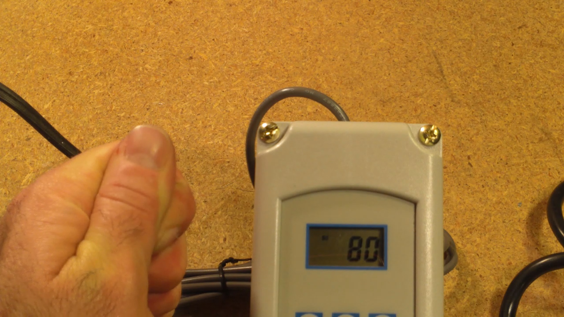
As you can see, the heater is plugged into my Ranco temperature controller. It’s telling me I’m at 75 degrees F now inside the fermenter. When I first began it was 70 degrees F internally, and I haven’t applied any heat yet so just from the beginning fermentation process alone, it’s increased 5 degrees F.
To hang my temperature controller I just used a zip tie and large clip. I’m going to cover my fermenter up with a towel to keep out sunlight and this thing is ready to go. If it decides it needs the heat (it’s set at 70 degrees F) it will kick on and heat it up +/- 1 degree.
Heater Update
27:23 Just a quick update on how the heater has been going, it has been working really well. To help contain the heat I draped my towel over the edges of the pad and it really helps. I haven’t seen my internal temperature drop below 69 degrees F, even though it’s very cold outside. Overall it has been working really well and I’m happy with it.